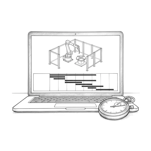
What is the difference between cycle time and takt time?
Cycle time is the measured time a station needs to finish one part. Takt time is the pace customer demand requires: available production time divided by the number of parts demanded. A line that runs 480 minutes a day and has to deliver 240 parts has a takt time of 2 minutes.
If a station's cycle time is longer than the takt time, that station is a bottleneck and demand can't be met. That is why the number in the quote is not enough on its own. The real question is whether the time measured on site will stay below takt.
Why do quoted cycle times miss on site?
Usually not because of a wrong calculation, but because of missing assumptions. The quoted figure predicts robot motion and weld time well and leaves out the moments when the robot waits. These are the most common gaps:
- Optimistic speeds and accelerations. In quote-stage simulation the robot often moves at full speed with generous zones. On site you add slowed approaches near clamps, safe retract points and paths that avoid singularities.
- Waits for clamps, sensors and PLC handshakes. A pneumatic clamp closing, a part-present sensor confirming, a handshake signal between PLC and robot: each takes a fraction of a second. A cycle contains dozens of them, and they easily add up to seconds.
- Operator loading time. The quote assumes loading is finished on the other station while the robot welds. With a heavy part, a part that is awkward to seat, or at the end of a shift, the robot waits for the operator.
- Tool changes and torch maintenance. Tool change time in cells with a tool changer, and nozzle cleaning and wire cutting in welding cells, should be spread over each part according to how often they happen.
- Vacuum build-up. With a vacuum gripper, the robot doesn't move until the vacuum switch confirms. That time depends on system volume and the generator's suction rate; Schmalz's worked example gives about 0.35 seconds for a small system, and it repeats at every pick and place.
- Safety speed limits. If the cell uses scanners that drop the robot to safe reduced speed when someone enters a zone, every cycle in which the operator comes close takes longer.
- Real part variation. If parts vary more than the drawing, touch sensing or seam finding gets added. Touch sensing can add several seconds per search direction.
How do you read a cycle time breakdown?
A good cycle time breakdown lists every step from the moment a part enters the cell to the moment it leaves, each on its own line, in seconds. A single total can't be checked; a breakdown can.
Read the lines in four groups:
| Group | What it contains | What to check |
|---|---|---|
| Robot motion | Approach, moves between seams, retract, return to home | Which speeds and zones were assumed? |
| Process time | Arc time (seam length divided by travel speed), screwing, pressing | Were weld speeds set from trial welds or taken from a table? |
| Waits | Clamps, sensors, PLC signals, vacuum, gas pre-flow | Are these lines in the quote at all? |
| Handling and loading | Turntable, conveyor, operator loading, tool change | Are the parallel steps really parallel? |
Look hard at the parallel steps. On a two-station turntable, the operator's loading time is invisible as long as it is shorter than the robot's weld time. The moment it gets longer, it goes straight onto the cycle time.
Example: a 60-second quote becomes 73 seconds on site
All figures below are illustrative and not taken from a real project. Picture a plant running two shifts, 450 net minutes per shift, 240 working days a year. Available time is 12,960,000 seconds a year. With an annual demand of 180,000 parts, takt time is 72 seconds.
| Step | Quoted | Measured on site |
|---|---|---|
| Turntable index | 3.0 s | 3.0 s |
| Clamp, sensor and PLC waits | not listed | 1.5 s |
| Robot motion | 21.0 s | 24.0 s |
| Welding (arc time) | 34.0 s | 34.0 s |
| Gas pre-flow and post-flow | not listed | 1.2 s |
| Nozzle cleaning and wire cutting (spread per cycle) | 2.0 s | 3.5 s |
| Waiting for the operator | not listed | 6.0 s |
| Total | 60.0 s | 73.2 s |
On paper the cell was 12 seconds under takt. On site it is 1.2 seconds over, which caps output at about 177,000 parts a year: roughly 3,000 short of demand. And that assumes the cell runs every planned minute without a stop; real output is lower by whatever downtime there is. Note that the weld time didn't change at all. Every lost second came from waits that were never written into the quote.
Is a tenth of a second really worth thousands of parts?
It is when the cycle is short, and it isn't when the cycle is long. In the same example plant, cutting a 10-second cycle to 9.9 seconds adds about 13,000 parts of capacity a year. On a 60-second welding cycle, the same tenth of a second is worth only about 360 parts.
One more caveat: extra capacity only turns into money if the cell really is the bottleneck and there is demand for the parts. In a cell running comfortably under takt, cutting downtime usually delivers more parts than chasing seconds.
What does simulation show, and what doesn't it?
Simulation shows, before anything is built, whether the robot can reach every point, whether anything collides and how long the motion takes. How realistic the motion time is depends on whether the simulation uses the robot maker's own motion planning software. ABB's RobotStudio is built on the Virtual Controller, which ABB describes as an exact copy of the software that runs its robots in production. General-purpose simulation tools can do the same through RRS (Realistic Robot Simulation), an interface started by automotive manufacturers that plugs the maker's controller software into the simulator.
The limit: simulation is only as accurate as the data it is given. KUKA says plainly, for its own simulation software, that the accuracy of cycle-time simulations depends on the quality of the models and project data. Clamp times, operator behaviour, dress-pack restrictions and real part variation only appear in a simulation if someone puts them into the model.
What does virtual commissioning add?
Virtual commissioning runs the real PLC program against the simulated cell. Siemens' S7-PLCSIM Advanced, for example, runs an S7-1500 program on a PC without hardware and can be connected to a machine simulation. Clamp sequences, handshake signals, fault states and restart logic can then be tested at a desk.
For cycle time, the value is that waits show up in the model driven by the real PLC logic. Why the robot is waiting for a "clamp closed" signal becomes visible on screen rather than on the shop floor.
How do you measure cycle time on site?
Timing a few parts with a stopwatch misleads. A useful measurement is split into the same steps as the quoted breakdown and covers a large number of cycles.
- Take timestamps from the system. Log a timestamp in the robot program and the PLC at the start and end of each step: part ready, clamps closed, arc on, arc off, turntable indexed. Each line can then be compared with the matching line in the breakdown.
- Look at the distribution, not one cycle. Check the average over hundreds of cycles, the slowest five percent and the single longest cycle separately. If the average holds but long cycles are frequent, the problem is usually a wait or the operator.
- Look at variation across the shift. Measure at the start and end of a shift, after breaks and with different operators. Operator-dependent steps vary most here.
- Record stoppages separately. Breakdowns, waiting for material and planned maintenance should not be mixed into cycle time. Cycle time describes how fast the cell runs; stoppages describe how available it is, and each needs a different fix.
What should you ask an integrator before signing?
- A step-by-step breakdown. Every step between part in and part out, each on its own line, in seconds.
- A list of assumptions. Robot model, speeds and zones, weld speeds and seam lengths, clamp and sensor times, operator loading time, nozzle cleaning and tool change frequency, safety zones.
- What the number includes. Robot motion only, or the full time from part in to part out? For the average part, or the longest variant?
- How the simulation was done. Which software, using the robot maker's controller model? Is the PLC logic in the model?
- The acceptance test definition. A run at rate: production at the target cycle time for a defined period, with real parts, production operators and no intervention. In automotive this typically lasts a full shift, and good parts produced are compared with the target.
- What happens if the target is missed. Time to fix, at whose cost, and when the test is repeated.
How Piot helps
We build and test robot cells virtually before installation and use cycle-time analysis to find bottlenecks before anything reaches the site. Our approach is described on the simulation and cycle time page. If you are planning a new robot cell or robotic welding cell, ask us the questions in this article too. We know simulation doesn't show real part variation, so during the first site visit we also look at your sample parts with that in mind.
Sources
- Lean Enterprise Institute: Takt time (definition and the 480-minute, 240-part example)
- Lean Enterprise Institute: Cycle time (definition of cycle time)
- Schmalz: Calculation of evacuation times (vacuum evacuation time, 0.35-second example)
- Control Design: What constitutes a safe speed? (safe reduced speed when a person enters the zone)
- ABICOR BINZEL: How Seam Tracking Solutions Compare (time added per touch-sensing search)
- ABB: RobotStudio (Virtual Controller as an exact copy of the real controller software)
- RoboDK: Realistic Robot Simulation (RRS) (standard for plugging the maker's controller software into simulation)
- Fraunhofer IPK: Realistic Robot Simulation (RRS) (RRS initiated by automotive companies)
- KUKA: Simulation, planning and optimization software, FAQ (accuracy of cycle-time simulation, virtual commissioning, PLC connectivity)
- Siemens: S7-PLCSIM Advanced (running S7-1500 programs without hardware, co-simulation with a machine model)
- TE Connectivity: Supplier Run@Rate Procedure (demonstrated vs quoted capacity, one-shift run)
- FlowFuse: Run at Rate: Proving Production Capacity Before Launch (timed production run at target cycle time, difference from a short trial)